domenica 15 novembre 2015

Using redis as a base for a spatial model

Recently I've been working with on a server application that could maintain the spatial location of its clients and make them query their neighbours. Following are listed some of the design choices for this project and we discuss how redis is perfect as a base for the spatial computing model.

Design

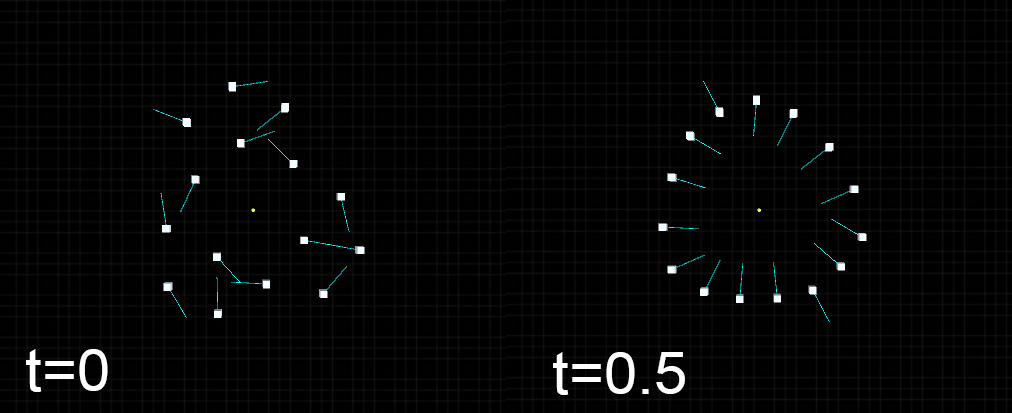
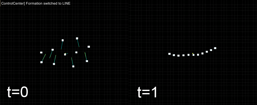
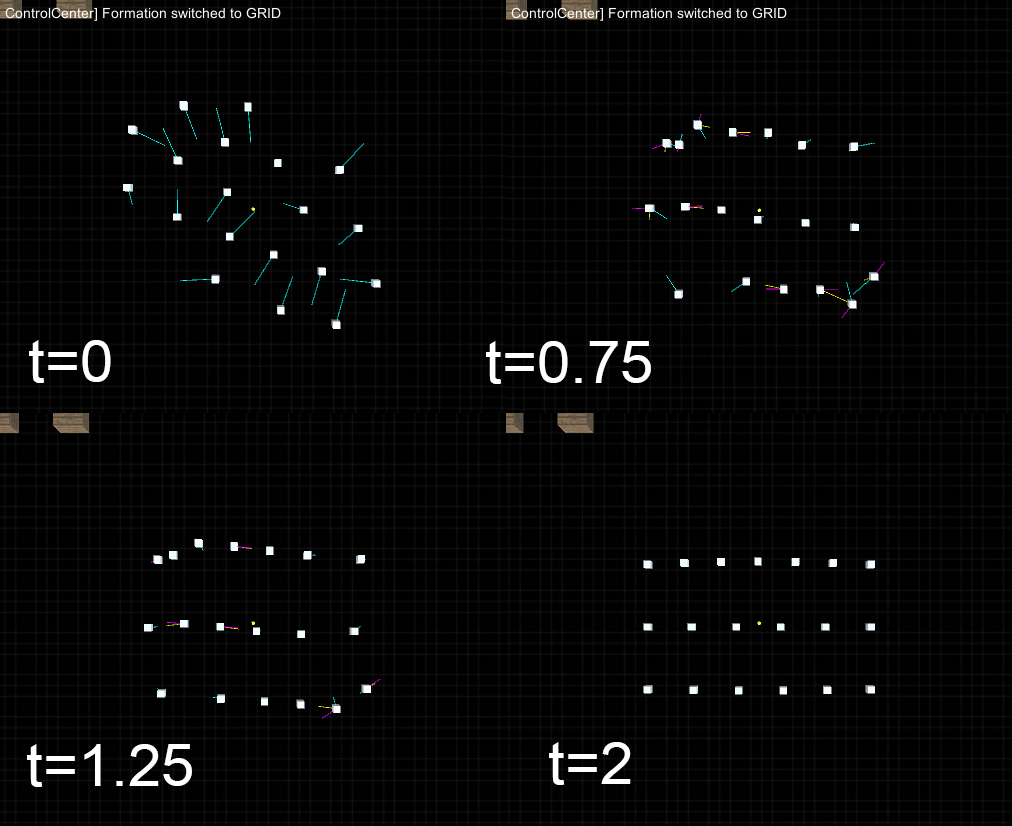
The system we want to build is a key component for the spatial computing system, its task is to mediate interactions between neighbours and maintain a consistent representation of the network of devices.

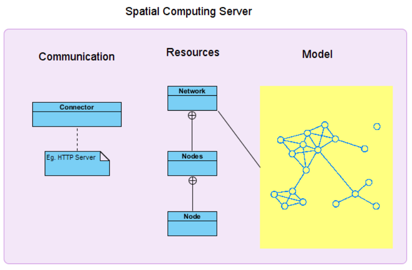
As shown in the picture, this system is made up of three exential logical parts.
The connector, is the component of the system that enables network communications between server and devices.
A resource is an object with a type, associated data, relationships to other resources, and a set of methods that operate on it. It models an important concept of the system that can be accessed remotely with standard methods like HTTP GET, POST and PUT.
The model must support a consistent representation of the device network and enables spatial query to be made considering the position of each node. Given the nature of the system, further consideration must be made on the model; data must be fresh and an outdated information must expire after a given time, querying the model should be fast and thread safe and must perform well even with large quantity of data.

In sight of simplicity and the fact that the server should be able to manage as much as requests as possible we decided to build a system that is based on the ReST model.
Using ReST architecture means using a simple client-server request/response protocol for communication, moreover it enables the designer to think about the concept of resource and its representation. Next we define what resources are made of and how they behave in relation to HTTP methods GET, PUT, POST, etc.

Redis Introduction

Redis is an open-source, in-memory data structure storage that is build to work with large quantity of data. It’s simple to use and with a well-made documentation, regardless it offers the following features that makes it perfect of our applicative scenario:

Redis has it’s own set of action that can be performed on data structures, the full set of commands includes:
  • SET and GET to store and fetch information using a key string.
  • SADD and ZADD to add items to a set or sorted set.
  • SREM and ZREM to remove an item from a set or sorted set.
  • GEOADD to add an item with longitude and latitude to a geo index.
  • GEORADIUS to get items from a geo index inside a radius of given meters from a point.

Redis Implementation

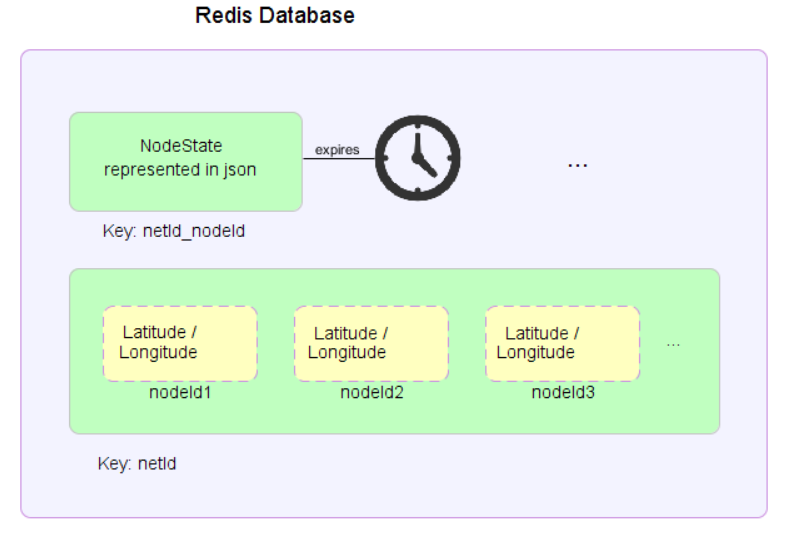
Information of one node should be indexed by the network id of our model and the node id itself, this means that we can use these two types of data structure for storing our model:
  • a simple string indexed with a combination of the netId and nodeId for saving all information about a note state (using for example json formalism).
    • that can be made expirable after a given amount of seconds.
  • a geospatial index (geolist) indexed by the netId containing all nodes at a given latitude and longitude.
    • that can be used for neighbourhood search.


The reason we don’t simply use the geospatial index is that redis can’t mark as expirable elements of the geospatial index as well for elements of sets and lists. This means that consistency between the geolist and active nodes in a network should be given by the application, this could be done every time we fetch nodes from a network in four simple steps:

  1. Get the list of node ids from the geolist
  2. For every id in the list fetch the respective string representation from the db
    1. if the string is null mark the node id for deletion.
    2. otherwise parse the string and save the node into a list.
  3. Remove all marked node ids from the geolist in a single redis call.
  4. Return the list of parsed nodes.

Of course because interleaving of these operation can occur, case in which a node is removed from the geospatial index even if it was just added to the network exists. However we consider the price of using synchronism too high to pay since in our scenario we have to deal with devices that continuously update their state and losing track of a device for a given time is expected.

For communicating with redis lettuce was used as a client api, no authentication mechanism was implemented, all needed informations are redis machine ip number and port location.

Redis Error Measurement

Quoting redis.io webpages on distance measurement from two geopoints: “The distance is computed assuming that the Earth is a perfect sphere, so errors up to 0.5% are possible in edge cases.”
We want to test some cases to assert the quality of the measurement for our applicative scenario.

We take some distinctive points in Cesena (Italy):

// Piazza del popolo 44.137199, 12.241922
LatLonPosition piazza = new LatLonPosition(44.137199, 12.241922);
String idPiazza = addNewNode(44.137199, 12.241922);
// Piazza (pappa reale) 44.137560, 12.241320
addNewNode(44.137560, 12.241320);
// Rocca 44.135996, 12.240365.
addNewNode(44.135996, 12.240365);
// via chiaramonti (biblioteca) 44.140027, 12.242564
addNewNode(44.140027, 12.242564);
// via sacchi 3 (facoltà) 44.139623, 12.243427
addNewNode(44.139623, 12.243427);

And we check near places in a range of 100m from Piazza del popolo using the provided range search of redis implemented in the system.

NBR:[
idPappaReale
[pos: [lat:44.13756,lon:12.24132], values: {}, sensors: {}]
Distance: 62.60068090367517
idPiazza
[pos: [lat:44.137199,lon:12.241922], values: {}, sensors: {}]
Distance: 0.0
]

As expected the system shows two nodes, one being the center of the range search. More tests confirms that the georadius function of redis returns the expected values, but since we want to study the quality of these results we check possible error in measuring the distance from two points because that could result in obtaining more or less points from georadius.

Using Google Maps to obtain the “real” distance between two points, we test and see error given by redis.

Real distance
Redis distance
Error
62.45 m
62.60 m
0,15 m
183.67 m
185.13 m
1,46
315.23 m
318.52 m
3,29
295.96 m
274.38 m
21,58
1.07 km
1.07 km
< 0.01 km
669.89 km
670.07 km
0,18 km
642.52 km
642.71 km
0,19 km

Data shows that redis measurement have an error in meters that increases based on the range used for the range search. However since in our scenario we are interested in short distance range search between 5m and 200m at least, the error provided by the application is marginal.

Repository


martedì 8 settembre 2015

cake quest


I think I've grown quite a fan of regular show trough the years, so when in latest episode: Birthday Gift Rigby decided to make a videogame for his friend, of course I took the chance to make a playable version of it. I know you won't be disappointed !

I really don't know why I invested 1 hour and half on making this, but I thought it might be funny! All credits and art goes obviously to regular show creators and cartoon network!

Download Links:
Windows version
Web version

Images


Episode preview

lunedì 20 luglio 2015

Experimenting with decentralized control for swarm shape formation

Abstract

Objective of the project is to experiment with a decentralized control for swarm shape formation in a virtual environment.
Approach taken to the problem is the use of motor schema for aggregation of different behaviour forces used to provide control and autonomy of the swarm in respect of the user and some simple task like obstacle avoidance.
The techniques proposed can be used as an approach to deal with shape formation of virtual entities in videogames or as means to create graphical effects in particle systems.

Introduction

Swarm systems are the one made by a collection of individual entities, all acting on their own to reach a global collective goal. This type of systems are becoming more and more common due to their highly flexibility and ability to react to change, usually inspired by natural biological systems they are now used in a variety of useful applications, like: map building, surveillance, exploration, etc.
For means of adaptability and control, while providing their main functionality, the swarm should be able to preserve or form a defined shape, like a sphere, a grid lattice or a line, moreover shape formation can be the main functionality of the swarm, like in an hunting-like environment where predators forms a circle around the prey. On the matter of swarm robots, shape formation is a topic already discussed in research, where most of the resources are focused on dealing with poor sensors capability and limits imposed by the physical world. Not so much is said about using this decentralized approach as an architecture for building interactive applications, like videogames, simulation environments, etc.
This document wants to focus on the practices used for building an interactive application that simulates shape formation for a group of agents in a predefined environment. We’ll focus on the decentralized approach used for forming a circle with variable diameter size, a simple line, a grid lattice with variable vertical lines and a sparse formation in respect of a fixed distance constraint. We’ll see how using the potential field movement schema we can aggregate different behaviours that offers a high flexibility in respect of coupling with multiple tasks, like obstacle avoidance, preserve separation and react to user control.

Assumptions

Since we are not dealing with robots but simple agents in a virtual environment, strong assumptions are made.
Agents knows their exactly position and rotation in space based on common coordinates of the scene, moreover agents have the ability to locate “peers” among the scene and determinate the exact distance from each of them (i.e. they have a “global” sensing capability as stated in [1] and [2]).
Usage of these pattern formation tec
\hniques can still be used on not-complex physical environment with respect of these assumptions, using gyroscopes and indoor or global positioning systems.

Development

Forming a circle

The method used for forming the shape of a circle is based on the CIRCLE Algorithm proposed in [1]. The objective of this algorithm is to form an approximation of a circle of diameter D, given the ability of the agent to perceive each of his peers.
Each agent R continuously monitors the distance from the furthest agent R’ and from the nearest agent R’’ and calculates the distance d between the two, then acts as follow:
  • Case 1. If d > D, then R moves toward R'.
  • Case 2. If d < D - δ, then R moves away from R'.
  • Case 3. If D - δ < d < D, then R moves away from R'.
Where δ is a small constant.
As [1] states, the form of a circle is assured by these three simple cases if the distribution of the agents in the space is uniform, however we overcome this limit by summing to the vector force that create the circle a separation vector force that distanciates peers.
Figure 1 shows results of the application compared to the ones of [1].

Forming a line

Forming a line segment is one of the simplest formation behaviour, all one agent R needs to do is to detect his nearest right peer r(R) and his nearest left peer l(R) and then move to the middle point of the r(R)l(R) segment. Agents that doesn’t have a right or left peer are the point of the line segment and shouldn’t move. Result of the algorithm as proposed in [1] is shown in figure 2.

Forming a sparse formation

Another interesting topology for a swarm is the one in which it’s parts are never too close, but either not too far apart. Using the dispersion method proposed in [2] one can control a swarm so that it doesn’t form a specific shape, but a more sparse and yet uniform in peer distance formation.
The dispersion method described in [2] was slightly modified to work better in a decentralized fashion and works as follows:
  • For every agent O find the three closest agents A,B and C
  • Initialize a force vector to zero
    • if distance of A from O is > d sum to the force vector an attractive force from O to A
    • if distance of A from O is < d sum to the force vector a repulsive force from A to O
  • do the same for B and C
  • apply the force vector to O
The constant d is a given min distance among peers.
Results of the algorithm are shown in the figure.

Forming a Grid Lattice

Different methods for obtaining a grid formation where experienced, however one only seems to show a better adaptability to change among others and it’s based on the use of a square formation algorithm and the line formation algorithm.
Since every agent has the ability to perceive each of his peers position in space, he can calculate the swarm center with a simple average function, then he can find which agents are the vertex of the grid by evaluating the distance vector of each agent from the center.
  • If the agent computing is a vertex, then he executes the square formation algorithm that constrains the x and z coordinates of the agents to form a square. Consider the agent A  vertex of the square formed by the agents ABCD, where A is the upper left edge, B the upper right and so on. A moves on the z axis so that it’s z is the same as B z, the same thing is done for the x coordinate.
  • If the agent computing is not a vertex he still has to compute the square based on his peers position, then he mentally divides the square in vertical zones, based on a given number v of desired vertical lines. Once the agent knows in which vertical zone of the grid he’s in, he execute the line segment algorithm only considering peers in the same vertical zone. If the agent is the edge of the segment, then he should move so that it’s x is the same as the square vertex.
Given an uniformed distribution of the agents in the space, these method produces a pretty good result, however one can surely notice that selection of the vertical zone is based on the initial position of the agent, so a correct grid needs a new force that can better arrange the agents during the formation.
This method is essentially different from the one proposed by [3] that implies an automatic or user controlled coordination between agents to create the grid. Comparison of the two methods is shown in the figures.

Swarm Control and Behaviour

The use of motor schema revealed fundamental for implementing different forces used for both control based on the user input and autonomous behaviour as evading objects.  

Control Forces

  • Movement: Used to move a selected agent in the scene.
  • Rotation: Makes the agent move around the center of the swarm, due to the algorithms used this force interferes with all the formations except for the circle.
  • Expansion/Contraction: The agent move away or towards the center of the swarm.

Other Forces

  • Formation: The force that permits the agent to form a specific pattern with his peers.
  • Avoidance: A force added when the agent perceives an obstacle on his way, due to the nature of the circle and dispersion algorithm the constraint imposed on a single agent prevents the whole swarm to move towards an obstacle. This isn’t the case for the line and grid formation however, that can move near and through obstacles and then recreate their formation. A trigger can be used for circle and dispersion formation to drop the use of the formation force when they perceive something on their path.
  • Separation: A simple separation force among the peers.

Conclusion

In this document we have presented ways of dealing with shape formation of a swarm in respect of some simple patterns like a circle, a line, a grid lattice and an uniform sparse formation. Building and using the application is a mean for experimenting with swarm control and their properties in a virtual environment.
The usage of a potential field pattern for aggregation of the precalculated forces in play revealed as the basic method to control the swarm with no particular drawbacks experienced.
This decentralized approach offers properties of adaptability to the environment, every agent works on his own in respect of the position of his peers, there’s no explicit leader or reference to other agents, as a result of this, there’s not a single point of failure and no need to update references when an agent is destroyed or created.
As the application is an interesting tool to experience with swarm shape formation, it’s always righteous to remember that problems arises when similar techniques are used in the real physical world.

References

[1] Distributed Algorithms for Formation of Geometric Patterns with Many Mobile Robots of Kazuo Sugihara and lchiro Suzuki*- Journal of Robotic Systems 13(3), 127-139 (1996) John Wiley & Sons, inc.
[2] Dispersion and Line Formation in Artificial Swarm Intelligence DONGHWA JEONG and KIJU LEE, Case Western Reserve University
[3] Decentralized control of multi-agent systems for swarming with a given geometric pattern - Teddy M. Cheng∗, Andrey V. Savkin

Download Link

Windows build of the application
C# class for shape formation